← Back 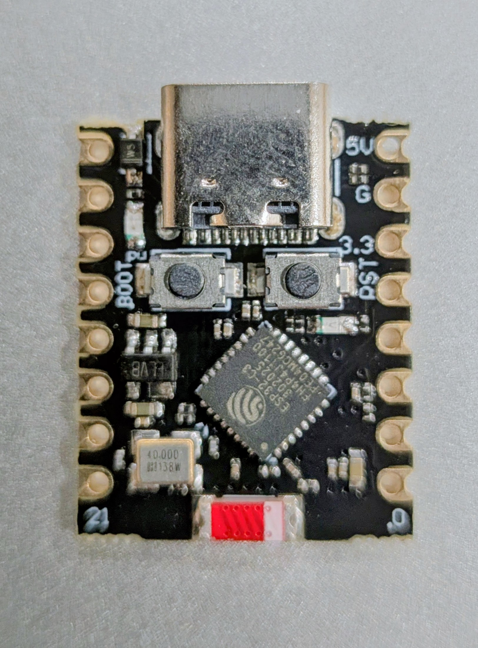
Microcontroller
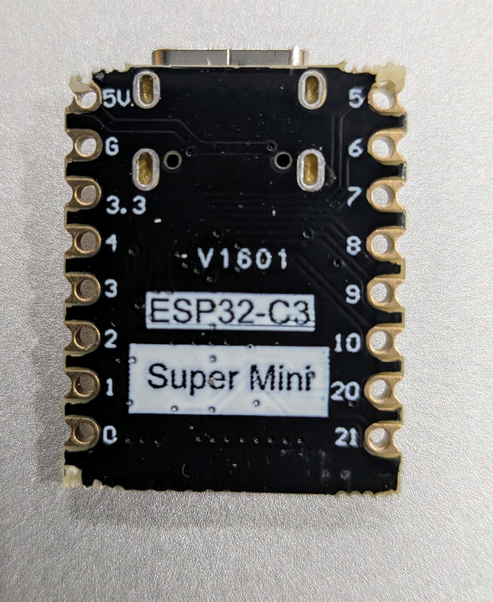
ESP32-C3
Using the ESP32-C3 with the MAX98357A guide - what changes, what stays the same
The ESP32-C3 is a single-core RISC-V microcontroller with WiFi and Bluetooth. It has one I2S peripheral and works with the MAX98357A guide - the only changes needed are the board selection in Arduino IDE and the three pin numbers in the sketch.
Pins to use
| ESP32-C3 Pin | MAX98357A Pin | Signal |
|---|---|---|
| 5V | VIN | Power |
| GND | GND | Common ground |
| GPIO4 | BCLK | I2S bit clock |
| GPIO5 | LRC | I2S word select (LRCLK) |
| GPIO6 | DIN | I2S data out from ESP32-C3 |
Pins to avoid
| GPIO range | Why to avoid |
|---|---|
| GPIO0 | Boot strapping pin - affects startup mode |
| GPIO8, GPIO9 | Strapping pins - can interfere with flashing |
| GPIO11-17 | SPI flash - connected to internal flash chip |
| GPIO18, GPIO19 | USB D- / D+ on boards with USB-CDC |
Sketch changes
The guide sketches already include the ESP32-C3 pin defines as commented-out alternatives. Comment out the ESP32 Dev Board lines and uncomment the C3 lines:
// comment these out:
//#define I2S_BCLK   27
//#define I2S_LRCLK  14
//#define I2S_DOUT   13

// uncomment these:
#define I2S_BCLK   4
#define I2S_LRCLK  5
#define I2S_DOUT   6
The guide uses the legacy I2S driver which works on ESP32-C3 with Arduino-ESP32 v2.x, and still compiles on v3.x with deprecation warnings. Everything else in the sketch stays the same.
Arduino IDE settings
| Setting | Value |
|---|---|
| Board | ESP32C3 Dev Module |
| Partition Scheme | Huge APP (3MB No OTA) - same as the guide |
| USB CDC On Boot | Enabled (needed if you use Serial.print for debugging) |
What stays the same
- Wiring to the MAX98357A module - pin functions are identical
- Audio preparation with espeak-ng and ffmpeg
- WAV-to-header Python script
- The rest of the sketch - I2S config, DMA setup, playback loop
Key details
- Use GPIO4 (BCLK), GPIO5 (LRC), GPIO6 (DIN)
- Select "ESP32C3 Dev Module" in Arduino IDE
- Only change needed in the sketch: the three pin #defines
- Same wiring to MAX98357A, same audio prep, same partition scheme
- Avoid GPIO8, GPIO9, and GPIO11-17