The car
Bought it four years ago, the first year my son was born. Under 200,000km, mint condition. $1200 from a bloke who’d inherited it and just wanted it gone. The plan was always the same: keep it, look after it, hand it over when he’s old enough. By then it’ll be an antique.
The previous owner must have had a lot of dogs. A lot of dogs. It took hours of vacuuming and months of odour treatment before it was liveable. Four years on, on a 40 degree summer day with the windows up, you still catch a whiff of the old boys.
When the ECU died I was gutted. And then almost immediately completely stoked. Because the problem that had just presented itself was: build an ECU. From scratch. For a 30-year-old Jeep. That’s not a setback. That’s a project. A terrifying one, with real consequences if I get it wrong.
The failed repair
First attempt: caps. One was visibly bulged, which felt like a clean diagnosis. Pulled it, replaced it. Still dead. Went back in and reflowed the board — or as much of it as was accessible, which isn’t much when half the components are buried under potting compound. No joy.
At that point the options were: second-hand ECU, aftermarket replacement, or something else entirely. Second-hand units were listing for $350–$800. Still a 30-year-old part, still carrying 30 years of the same heat cycling, same aged solder, same unknown history. Paying $600 to have the same problem again in two years didn’t appeal. Aftermarket replacements existed — and started at well over a thousand dollars. Some pushing two. Not a chance.
Which left the third option.
The idea
The XJ’s factory PCM is a sealed black box from 1995. Literally sealed — the board is potted in epoxy resin, which made sense for vibration resistance in 1995 and makes repair nearly impossible in 2026. An open-source replacement fixes that entirely. Full tunability, real-time data logging, and a codebase you can actually read and modify.
The Speeduino project is exactly this: an open-source, Arduino-based engine management system designed to replace factory ECUs. The v0.4 board is the universal workhorse of the platform. The 4.0L inline-six is a relatively simple engine — no variable timing, no drive-by-wire, no nonsense. One coil, six injectors, two sensors for crank and cam position. On paper, a clean project.
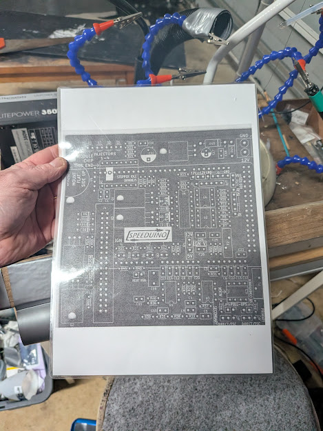 The full board schematic printed out for reference during the build. Both the Speeduino manual and the XJ factory service manual need to be open at the same time.
The XJ is right-hand drive, which matters for one reason: the factory wiring diagrams have separate RHD variants, and the PCM connector pinout differs from the LHD documentation that shows up in most online guides. Working from the original 1995 factory service manual throughout.
The platform
The tuning laptop is an Asus E510 running Arch Linux with i3 as the window manager. Single purpose — this machine exists for this project. It’s how the garage runs: each laptop gets one job and does it without distraction. PlatformIO handles firmware compilation. TunerStudio handles configuration and real-time tuning. The Arduino communicates over USB serial at 115,200 baud, appearing as /dev/ttyUSB0 with the CH340G chip.
One early gotcha on Arch: serial port access requires the uucp and lock groups, not dialout as it would be on a Debian-based system. Group membership doesn’t take effect until you log out fully — in i3 that’s Mod+Shift+E. An hour’s debugging traced back to missing group membership.
TunerStudio is available from tunerstudio.com/downloads2/ — the efianalytics.com URL returns a 404. Not obvious if you’re coming in from old forum posts.
The board
The v0.4.4b is a through-hole design. Every component leads through the board and gets soldered on the back — slower than SMD but easier to rework, easier to inspect, and forgiving of a less than perfect iron.
The BOM kit arrives as a single bag of mixed components — ten of this, five of that, all in together. The process is to work through the BOM list one line at a time, pull the right part from the bag, place it, solder it, and mark it off on the bag as you go. Slow and methodical beats fast and wrong when the end result is going into a running engine.
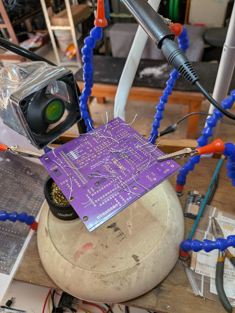 Board mid-build in the helping hands. Through-hole throughout — methodical work, one section at a time.
What the factory system does
The stock PCM controls everything fuel and ignition related. Replacing it means taking over every function it performed.
Inputs the PCM reads:
- Crankshaft Position Sensor (CPS) — RPM and crank angle, Hall effect
- Camshaft Position Sensor — cam sync for sequential injection, Hall effect
- MAP sensor — engine load
- TPS — throttle position
- ECT — coolant temperature
- IAT — intake air temperature
- O2 sensor — closed-loop fuel correction
- Vehicle Speed Sensor
Outputs the PCM drives:
- 6 x sequential fuel injectors
- Ignition timing (via igniter module - not direct to coil)
- Idle Air Control motor
- Fuel pump relay (ASD relay)
- Tachometer signal
The injectors are high-impedance (high-Z, saturated circuit). Speeduino supports these natively without peak-and-hold or ballast resistors.
The ignition output goes through the factory igniter module, not directly to the coil. The Speeduino fires the igniter, the igniter drives the coil. This is intentional — the coil primary current is too high for the ECU output pin to handle directly.
Trigger setup
This is the part that has to be right before anything else matters.
The 4.0L crank and cam sensors are both Hall effect type. On the Speeduino v0.4 board this means:
- JP4 and JP5 jumpers: ON (enables pull-up resistors for Hall sensors)
- JP2 and JP3: set to Hall / Direct (not VR conditioner path)
Get this wrong and the ECU never sees a valid trigger signal. The engine cranks and refuses to fire.
Firing order for the 4.0L: 1-5-3-6-2-4. Sequential injection requires the cam sensor for cylinder identification. Without a valid cam sync signal, Speeduino falls back to batch injection — it’ll run, but you lose the sequential advantage.
The RHD wrinkle
Most Speeduino XJ documentation online assumes a left-hand drive North American vehicle. The RHD variant has different PCM connector pinouts. The factory service manual has separate wiring diagrams for the RHD configuration — these are the source of truth. Any online guide that doesn’t specify LHD or RHD should be treated with suspicion and verified against the factory documentation before a wire gets cut.
Progress
Done:
- Firmware compiled with PlatformIO (
megaatmega2560) and flashed to the blue Elegoo Mega — confirmed running Speeduino2025.04-dev - TunerStudio installed, project
xj_4.0_RDHcreated, live dashboard confirmed - i3 bar launcher configured for TunerStudio
- Key engine parameters established: cylinders, displacement, firing order, injector type, trigger configuration
- RHD wiring diagrams located in factory service manual and cross-referenced against Speeduino pinout
In progress:
- Building the pin translation table: stock PCM connector to Speeduino inputs/outputs
- TunerStudio XJ-specific configuration
Not started:
- Physical wiring
- Bench testing on a power supply before installation
- Installation in the car
Build log updated as the project progresses.