← Back 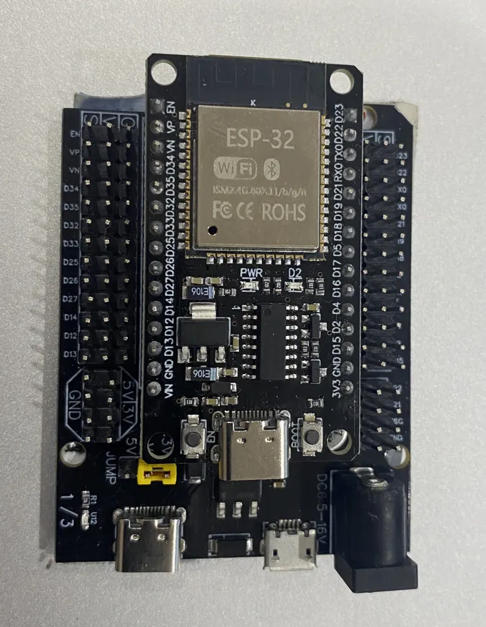
Microcontroller
ESP32 Dev Board
38-pin development board - SPI display pins for the GC9D01 guide
Official Espressif documentation:
ESP32-DevKitC V4 user guide →The ESP32 is a dual-core 240MHz microcontroller with built-in WiFi and Bluetooth. The 38-pin dev board breaks all GPIO pins out on two rows of headers.
SPI displays use the ESP32's hardware SPI peripheral. GPIO18 and GPIO23 are the default hardware SPI clock and data pins - using these gives maximum SPI speed. DC, CS, and RST can be any available GPIO.
Pins used in this guide
| ESP32 Pin | GC9D01 Pin | Signal |
|---|---|---|
| 3.3V | VCC | Power (3.3V only - no 5V tolerance) |
| GND | GND | Common ground |
| GPIO18 | SCL | SPI clock (hardware SPI default) |
| GPIO23 | SDA | SPI data / MOSI (hardware SPI default) |
| GPIO27 | DC | Data / command select |
| GPIO5 | CS | Chip select |
| GPIO4 | RST | Reset |
| 3.3V | BL | Backlight - wire to 3.3V for always-on |
Why not GPIO2 for DC?
GPIO2 is a boot strapping pin on the ESP32. The display holds DC low during SPI transfers, which at boot puts the ESP32 into download mode - upload failures every time. GPIO27 has no boot-strapping function and works correctly.
Key details
- GPIO18 - SPI clock (SCL) → GC9D01 SCL
- GPIO23 - SPI data (SDA/MOSI) → GC9D01 SDA
- GPIO27 - Data/command select → GC9D01 DC
- GPIO5 - Chip select → GC9D01 CS
- GPIO4 - Reset → GC9D01 RST
- 3.3V - Power and backlight (3.3V ONLY for this display)