How to use the
ST7735 128x128 display
with ESP32
Overview
The ST7735 is a 128x128 TFT display driven over SPI. It is one of the most common small TFT displays for ESP32 projects. Several colour tab variants exist - if colours look wrong after setup, see the Notes section.
This page covers the User_Setup_Select.h config to drive it with TFT_eSPI. Once configured, use the How to set up TFT_eSPI with ESP32 - test sketch to confirm it is working.
Wiring
| Display Pin | ESP32 Pin | Notes |
|---|---|---|
| VCC | 3.3V or 5V | 5V tolerant on tested module - confirm with your board's datasheet |
| GND | GND | |
| SCL / SCLK | GPIO 18 | SPI clock |
| SDA / MOSI | GPIO 23 | SPI data |
| DC / A0 | GPIO 2 | Data / command select |
| CS | GPIO 15 | Chip select |
| RST | GPIO 4 | Reset |
| MISO | GPIO 19 | Optional |
If your module has a BL (backlight) pin, tie it to 3.3V.
Config
1. Open User_Setup_Select.h
Open ~/Arduino/libraries/TFT_eSPI/User_Setup_Select.h. Comment out the default line and uncomment Setup47:
//#include <User_Setup.h>           // comment this out
#include <User_Setups/Setup47_ST7735.h>  // uncomment this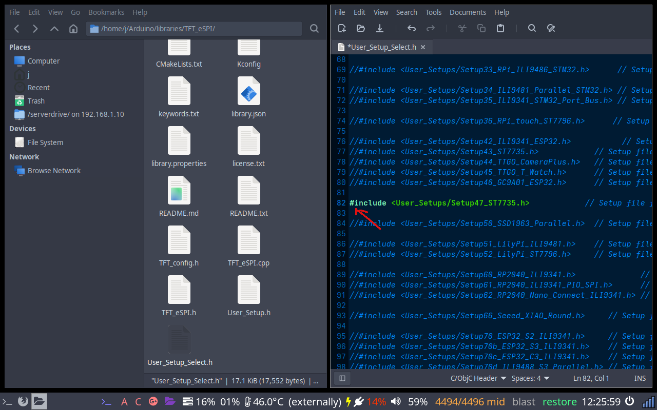
User_Setup_Select.h - Setup47 uncommented
2. Add CS pin to Setup47
Open ~/Arduino/libraries/TFT_eSPI/User_Setups/Setup47_ST7735.h. CS is commented out by default - uncomment it and set it to GPIO 15:
#define TFT_CS 15 // uncomment and set to GPIO 15MOSI (23), SCLK (18), MISO (19), DC (2), and RST (4) are already correct - leave them as is.
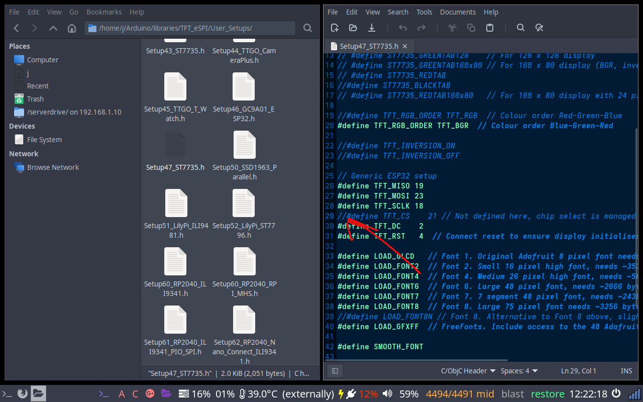
Uncomment the TFT_CS line
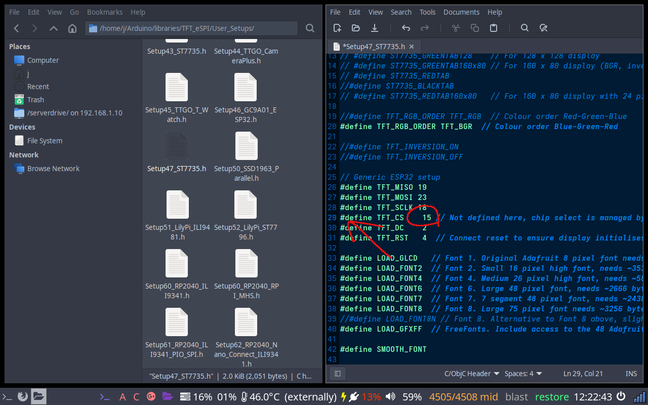
Change value from 21 to 15
Notes
Wrong colours - red and blue swapped
The ST7735 comes in several tab variants with different colour orders. If colours look inverted, try uncommenting #define TFT_RGB_ORDER TFT_BGR or TFT_RGB in the setup file.
ST7735 tab variants
The setup file includes defines like ST7735_REDTAB, ST7735_GREENTAB, ST7735_BLACKTAB. If the display initialises but the image is offset or scrambled, try a different tab define. Your module's product listing usually states which variant it is.