How to set up
TFT_eSPI with ESP32
Why TFT_eSPI
Most display guides pick one display and one library. That works until you get a second display, swap to a smaller board, or try to reuse code across projects - and suddenly you are learning a new API from scratch.
TFT_eSPI by Bodmer solves this. It is a single library that supports dozens of SPI display controllers - ST7735, ST7789, GC9A01, ILI9341, and more - all with the same API. To switch displays, you change a config file. The sketch stays the same.
"One library to rule them all, one library to find them,
one library to drive them all and in the PROGMEM bind them."
User_Setup.h config - which driver, which pins, what speed.
It is also the fastest option on ESP32, using hardware-accelerated SPI with optional DMA. The community is large and it is actively maintained.
How it compares
| Library | Displays supported | API changes per display | ESP32 speed |
|---|---|---|---|
| TFT_eSPI | Dozens (config-driven) | No - same sketch | Fast (hardware SPI + DMA) |
| Adafruit GFX | Per chip library | Yes - new lib per display | Moderate |
| Arduino_GFX | Many (constructor-driven) | Partial - constructor changes | Fast |
How It Works
Most libraries take pin numbers as constructor arguments in your sketch. TFT_eSPI works differently - display configuration lives in a setup file inside the library folder. You tell it which driver chip, which pins, and what SPI speed. The sketch itself has no pin numbers at all.
TFT_eSPI ships with a folder of ready-made setup files in User_Setups/ - one per display and board combination. A separate file called User_Setup_Select.h controls which one is active - only one line is uncommented at a time.
To switch displays, you comment out the current line and uncomment your next display's line. The sketch never changes. Each display config page on this site tells you exactly which setup file to use and which pin values to update.
~/Arduino/libraries/TFT_eSPI/User_Setup_Select.h - one uncommented line here controls everything.
Step 1 - Install the Library
Parts
- ESP32 Dev Board (38-pin)
- GC9A01 240x240 round IPS TFT (used as example - swap for any supported display)
- Jumper wires
- USB data cable for flashing
Install TFT_eSPI
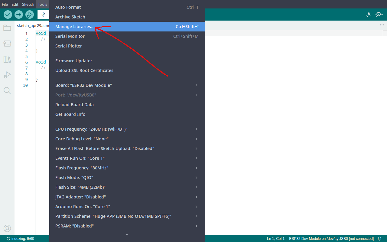
- Open Arduino IDE
- Go to Tools → Manage Libraries
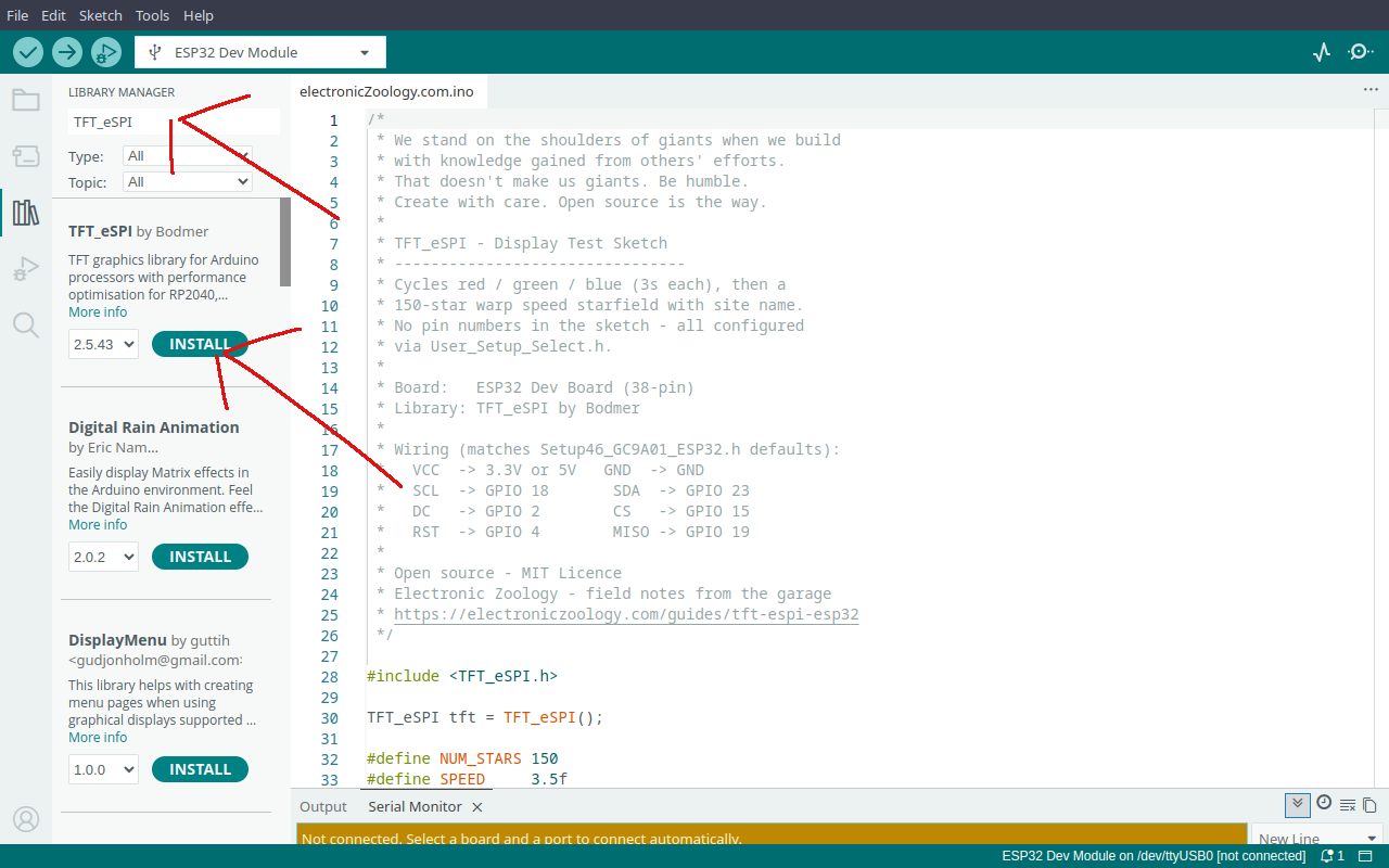
- In the search box type TFT_eSPI
- Several results will appear - find the one by Bodmer and click Install
Once installed, close and reopen Arduino IDE before continuing. The IDE needs a fresh start to pick up the new library correctly.
After reopening, the library folder will be at ~/Arduino/libraries/TFT_eSPI/. Inside you will find User_Setup_Select.h and a User_Setups/ folder - these are what you will edit in Step 2.
Step 2 - Pick Your Display
TFT_eSPI supports almost every SPI display available - ST7735, ST7789, GC9A01, ILI9341, ILI9488, and dozens more. If you bought an SPI TFT display, there is almost certainly a ready-made setup file for it already sitting in the User_Setups/ folder. The config pages below cover the displays confirmed working on this site.
| Display | Size | Status | Config Page |
|---|---|---|---|
| ST7735 | 128x128 | ✓ Confirmed | How to use the ST7735 128x128 display with ESP32 → |
| ST7789 | 240x240 | ✓ Confirmed | How to use the ST7789 240x240 display with ESP32 → |
| GC9A01 | 240x240 round | ✓ Confirmed | How to configure the GC9A01 round display with TFT_eSPI → |
Step 3 - Wire It Up
All SPI displays use the same five signals. The pin numbers below are the defaults used across all config pages on this site - consistent wiring means you can swap displays without rewiring.
| Display Pin | ESP32 Pin | Notes |
|---|---|---|
| VCC | 3.3V or 5V | Check your module - most accept both |
| GND | GND | |
| SCL / SCLK | GPIO 18 | SPI clock - hardware SPI default |
| SDA / MOSI | GPIO 23 | SPI data - hardware SPI default |
| DC | GPIO 2 | Data / command select |
| CS | GPIO 15 | Chip select |
| RST | GPIO 4 | Reset |
| MISO | GPIO 19 | Optional - connect if your module has it |
No MISO connection needed - SPI displays are write-only. Check your display's config page if your module labels pins differently.
Step 4 - Test Sketch
Flash this to confirm wiring and config are both correct. Cycles red, green, blue (3 seconds each), then a 150-star warp speed starfield with the site name overlaid.
/*
 * We stand on the shoulders of giants when we build
 * with knowledge gained from others' efforts.
 * That doesn't make us giants. Be humble.
 * Create with care. Open source is the way.
 *
 * TFT_eSPI - Display Test Sketch
 * --------------------------------
 * Cycles red / green / blue (3s each), then a
 * 150-star warp speed starfield with site name.
 * No pin numbers in the sketch - all configured
 * via User_Setup_Select.h.
 *
 * Board:   ESP32 Dev Board (38-pin)
 * Library: TFT_eSPI by Bodmer
 *
 * Wiring (matches Setup46_GC9A01_ESP32.h defaults):
 *   VCC  -> 3.3V or 5V   GND  -> GND
 *   SCL  -> GPIO 18       SDA  -> GPIO 23
 *   DC   -> GPIO 2        CS   -> GPIO 15
 *   RST  -> GPIO 4        MISO -> GPIO 19
 *
 * Open source - MIT Licence
 * Electronic Zoology - field notes from the garage
 * https://electroniczoology.com/guides/how-to-set-up-tft-espi-esp32
 */

#include <TFT_eSPI.h>

TFT_eSPI tft = TFT_eSPI();

#define NUM_STARS 150
#define SPEED     3.5f

struct Star { float x, y, z; int px, py; };
Star stars[NUM_STARS];

int CX, CY;

void resetStar(Star &s) {
  s.x  = random(-CX, CX);
  s.y  = random(-CY, CY);
  s.z  = random(60, 240);
  s.px = -1;
  s.py = -1;
}

uint16_t grey(uint8_t v) {
  return ((v >> 3) << 11) | ((v >> 2) << 5) | (v >> 3);
}

void printCentered(const char* text, int y) {
  int len = strlen(text);
  int size = 1;
  for (int s = 4; s >= 1; s--) {
    if (len * 6 * s <= tft.width() - 4) { size = s; break; }
  }
  tft.setTextSize(size);
  tft.setCursor((tft.width() - len * 6 * size) / 2, y);
  tft.print(text);
}

void drawTitle() {
  tft.setTextColor(TFT_WHITE);
  tft.setTextSize(2);
  printCentered("Electronic", CY - 18);
  printCentered("Zoology",    CY + 2);
}

void setup() {
  tft.init();
  tft.setRotation(0);
  randomSeed(analogRead(0));

  CX = tft.width()  / 2;
  CY = tft.height() / 2;

  tft.fillScreen(TFT_RED);   delay(3000);
  tft.fillScreen(TFT_GREEN); delay(3000);
  tft.fillScreen(TFT_BLUE);  delay(3000);
  tft.fillScreen(TFT_BLACK);

  for (int i = 0; i < NUM_STARS; i++) {
    resetStar(stars[i]);
    stars[i].z = random(1, 240);
  }
}

void loop() {
  for (int i = 0; i < NUM_STARS; i++) {
    Star &s = stars[i];

    if (s.px >= 0) {
      tft.fillCircle(s.px, s.py, s.z > 120 ? 1 : 2, TFT_BLACK);
    }

    s.z -= SPEED;
    if (s.z <= 1) { resetStar(s); continue; }

    int sx = CX + (int)(s.x * (float)CX / s.z);
    int sy = CY + (int)(s.y * (float)CY / s.z);

    if (sx < 0 || sx >= tft.width() || sy < 0 || sy >= tft.height()) {
      resetStar(s); continue;
    }

    uint8_t brightness = (uint8_t)((1.0f - s.z / 240.0f) * 220 + 35);
    int     radius     = s.z < 80 ? 2 : 1;

    tft.fillCircle(sx, sy, radius, grey(brightness));
    s.px = sx;
    s.py = sy;
  }

  drawTitle();
  delay(1);
}Troubleshooting
White screen / no output
- Check
User_Setup.hhas the correct driver uncommented - Check wiring - DC and CS are the most commonly swapped pins
- Confirm RST is connected, not floating
Compile error: multiple drivers defined
- Only one
#define *_DRIVERline should be uncommented inUser_Setup.h - Open the file and comment out any extras
Wrong colours or mirrored image
- Try
tft.setRotation(1),2, or3in setup - Some ST7735 variants need a colour order flag in
User_Setup.h- see the ST7735 config page
Display works but is slow
- Increase
SPI_FREQUENCYinUser_Setup.h- try40000000(40MHz) - Confirm you are using hardware SPI pins (GPIO 18/23) - software SPI is much slower
Sketch compiled fine but nothing appears
- Re-check that
User_Setup.hwas saved before compiling - Arduino IDE caches the library - Close and reopen Arduino IDE, then re-compile and flash
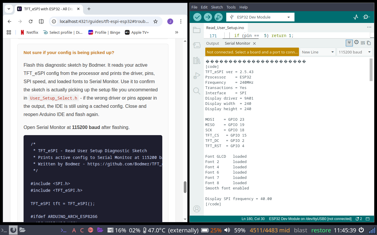
Not sure if your config is being picked up?
Flash this diagnostic sketch by Bodmer. It reads your active TFT_eSPI config from the processor and prints the driver, pins, SPI speed, and loaded fonts to Serial Monitor. Use it to confirm the sketch is actually picking up the setup file you uncommented in User_Setup_Select.h - if the wrong driver or pins appear in the output, the IDE is still using a cached config. Close and reopen Arduino IDE and flash again.
Open Serial Monitor at 115200 baud after flashing.
/*
 * TFT_eSPI - Read User Setup Diagnostic Sketch
 * Prints active config to Serial Monitor at 115200 baud.
 * Written by Bodmer - https://github.com/Bodmer/TFT_eSPI
 */

#include <SPI.h>
#include <TFT_eSPI.h>

TFT_eSPI tft = TFT_eSPI();

#ifdef ARDUINO_ARCH_ESP8266
  ADC_MODE(ADC_VCC);
#endif

setup_t user;

void setup() {
  Serial.begin(115200);
  tft.init();
}

void loop(void) {
  tft.getSetup(user);
  Serial.print("\n[code]\n");
  Serial.print("TFT_eSPI ver = "); Serial.println(user.version);
  printProcessorName();
  Serial.print("Transactions = "); Serial.println((user.trans  == 1) ? "Yes" : "No");
  Serial.print("Interface    = "); Serial.println((user.serial == 1) ? "SPI" : "Parallel");
  if (user.tft_driver != 0xE9D) {
    Serial.print("Display driver = "); Serial.println(user.tft_driver, HEX);
    Serial.print("Display width  = "); Serial.println(user.tft_width);
    Serial.print("Display height = "); Serial.println(user.tft_height);
    Serial.println();
  }
  if (user.pin_tft_mosi != -1) { Serial.print("MOSI    = GPIO "); Serial.println(user.pin_tft_mosi); }
  if (user.pin_tft_miso != -1) { Serial.print("MISO    = GPIO "); Serial.println(user.pin_tft_miso); }
  if (user.pin_tft_clk  != -1) { Serial.print("SCK     = GPIO "); Serial.println(user.pin_tft_clk); }
  if (user.pin_tft_cs   != -1) { Serial.print("TFT_CS  = GPIO "); Serial.println(user.pin_tft_cs); }
  if (user.pin_tft_dc   != -1) { Serial.print("TFT_DC  = GPIO "); Serial.println(user.pin_tft_dc); }
  if (user.pin_tft_rst  != -1) { Serial.print("TFT_RST = GPIO "); Serial.println(user.pin_tft_rst); }
  Serial.println();
  if (user.serial == 1) { Serial.print("SPI frequency = "); Serial.println(user.tft_spi_freq / 10.0); }
  Serial.println("[/code]");
  delay(3000);
}

void printProcessorName(void) {
  Serial.print("Processor = ");
  if (user.esp == 0x8266) Serial.println("ESP8266");
  if (user.esp == 0x32)   Serial.println("ESP32");
  if (user.esp == 0x32F)  Serial.println("STM32");
  if (user.esp == 0x2040) Serial.println("RP2040");
  if (user.esp == 0x0000) Serial.println("Generic");
}A correct config will look something like this in Serial Monitor: