How to build an INA219
battery charger monitor
with ESP32 and OLED
What this guide builds on
- How to check a new ESP32 - board setup in Arduino IDE, confirming the board is working before you build on it
- How to find your I2C address - how I2C addressing works and how to scan the bus to confirm your device is connected before writing a single line of project code
- How to use the SSD1306 OLED display with ESP32 - I2C wiring, library setup, and a test sketch to confirm the display is working
What You Will Learn
If you are charging lithium cells, you need to know what is going on. Dodgy modules can cook batteries. Counterfeit protection ICs lie. Salvaged cells from old laptop packs accept current in ways that depend on their history, and you cannot tell a tired cell from a healthy one without measuring. None of this is paranoia. It is just the cost of working with chemistry that might just want to give you a bad day. A red LED tells you nothing. Amps and volts tell you everything.
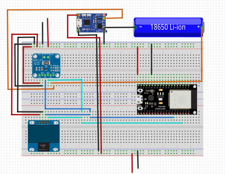
This guide builds the simplest possible answer to "what is actually happening on this charger." An INA219 sits inline between a TP4056 charger module and a single 18650 cell. An ESP32 reads voltage and current from the INA219 and shows both on an SSD1306 OLED. The meter sits next to the charger, watching, all the way from a flat cell to a full one. You see the entire charge curve unfold on the screen.
The INA219 is a high-side current sensor with an I2C interface. It measures the voltage drop across a small shunt resistor in the power line and converts that to current using Ohm's law internally. It also measures the bus voltage on the load side. Two readings, one chip, two signal wires. The SSD1306 OLED is also I2C - so the entire display side of this build shares the same SDA and SCL lines as the sensor. Four wires total for sensor and display combined.
You will also learn what a healthy charge cycle looks like. The current starts high and stays roughly constant. The voltage climbs slowly. Then the voltage hits 4.2V, the current starts tapering, and the cell sips the last few percent until the charger calls it done. That shape is called CC/CV - constant current, then constant voltage. Once you have watched it happen on your own bench you will recognise the shape forever.
Hardware
Parts
- ESP32 Dev Board - 30-pin or 38-pin module on a breadboard-friendly carrier
- INA219 breakout - common modules from any maker supplier all use the same chip and pinout. Default I2C address is
0x40 - SSD1306 128x64 OLED (4-pin I2C) - default address
0x3C. See How to use the SSD1306 OLED display with ESP32 if you have not used this display before - TP4056 module with battery protection - the two-IC version. The bare TP4056 works but a protected module is safer for bench experiments
- Single 18650 cell - any healthy cell. If you are charging a salvaged or unknown cell, that is exactly what this rig is for
- 18650 holder, or clip leads for brief testing
- Separate USB power sources for the TP4056 and the ESP32 - the ESP32 cannot share power with the cell being measured, otherwise the INA219 sees the chip's current overhead too
Software
- Arduino IDE with ESP32 board support
Adafruit INA219by AdafruitAdafruit SSD1306by AdafruitAdafruit GFX Libraryby Adafruit (dependency - click Install All when prompted)
Wiring
The INA219 sits inline on the positive line between the TP4056 and the battery. All negatives share a common ground.
Positive line: TP4056 B+ → INA219 VIN+ → INA219 VIN- → Battery +
Negative line: Battery - → TP4056 B- → Common GND (ESP32, INA219, OLED)
The INA219 and SSD1306 OLED both run on I2C and share the same two signal wires. You can daisy chain them - run SDA and SCL from the ESP32 to the first module, then on to the second - or split the signal and run parallel wires to both. Either way works because I2C is a bus, not a point-to-point link. Full pin table for an ESP32 Dev Board:
| ESP32 Pin | Connects to |
|---|---|
| GPIO 21 (SDA) | INA219 SDA, OLED SDA |
| GPIO 22 (SCL) | INA219 SCL, OLED SCL |
| 3.3V | INA219 VCC, OLED VCC |
| GND | INA219 GND, OLED GND, battery negative |
The TP4056 and ESP32 are on separate USB supplies.
0x40. SSD1306 defaults to 0x3C. They do not conflict. If you are unsure of your OLED's address, flash the I2C scanner from the SSD1306 guide first - it will report both devices on the bus.
The Sketch
Install two libraries from the Arduino IDE library manager:
- Adafruit INA219 by Adafruit
- Adafruit SSD1306 by Adafruit (installs Adafruit GFX as a dependency - click Install All when prompted)
The top line shows live voltage and current, updating five times a second. Below that, two views rotate every 5 seconds. The live view shows the last 25 seconds of current - 128 samples at 200ms, newest on the right. The charge view shows up to 2 hours of history - 128 samples at 60s - so you can watch the full CC/CV curve build across a whole charge. LIVE or CHARGE appears top-centre so you always know which view you are on. The charge view is empty for the first minute; it fills in as the charge progresses.
/*
 * We stand on the shoulders of giants when we build
 * with knowledge gained from others' efforts.
 * That doesn't make us giants. Be humble.
 * Create with care. Open source is the way.
 *
 * INA219 Monitor - Scrolling Graph Edition
 * -----------------------------------------
 * Reads voltage and current from an INA219 and displays both
 * numerically and as a scrolling graph on an SSD1306 OLED.
 *
 * Two views rotate automatically every VIEW_ROTATE_MS milliseconds:
 *
 *   Live view:   128 samples at 200ms = ~25 seconds of history
 *                Shows real-time behaviour, ripple, spikes.
 *
 *   Charge view: 128 samples at 60s = ~2 hours of history
 *                Shows the full CC/CV curve as a charge progresses.
 *                Resets on boot. Empty until the first minute passes.
 *
 * Both views share the same numeric top line (live voltage and current).
 * The view label (LIVE / CHARGE) appears top-centre during rotation.
 *
 * Use it to watch a TP4056 charge an 18650, or to watch an ESP32
 * sleep and wake during RTO testing. Same sketch, same wiring.
 *
 * Board:   ESP32 Dev Board (38-pin)
 * Library: Adafruit INA219 by Adafruit
 *          Adafruit SSD1306 + Adafruit GFX by Adafruit
 *
 * Wiring:
 *   INA219 + OLED: SDA -> GPIO 21   SCL -> GPIO 22
 *   Both:          VCC -> 3.3V      GND -> GND
 *   INA219 inline: VIN+ from supply, VIN- to load
 *
 * Open source - MIT Licence
 * Electronic Zoology - field notes from the garage
 * https://electroniczoology.com/guides/how-to-build-ina219-charger-monitor-esp32
 */

#include <Wire.h>
#include <Adafruit_INA219.h>
#include <Adafruit_GFX.h>
#include <Adafruit_SSD1306.h>

#define SCREEN_WIDTH     128
#define SCREEN_HEIGHT    64
#define OLED_RESET       -1
#define OLED_ADDRESS     0x3C    // Change to 0x3D if needed

#define GRAPH_MAX_MA     1200.0f

#define LIVE_SAMPLE_MS   200     // 5 samples/sec, 128 samples = ~25s
#define CHARGE_SAMPLE_MS 60000   // 1 sample/min, 128 samples = ~2hr

#define VIEW_ROTATE_MS   5000    // how long each view shows before flipping

#define GRAPH_Y          10
#define GRAPH_H          (SCREEN_HEIGHT - GRAPH_Y)   // 54px
#define BUF_SIZE         SCREEN_WIDTH                // 128 points

Adafruit_SSD1306 display(SCREEN_WIDTH, SCREEN_HEIGHT, &Wire, OLED_RESET);
Adafruit_INA219   ina219;

// Live buffer
float   liveBuf[BUF_SIZE];
uint8_t liveHead = 0;
bool    liveFull = false;

// Charge buffer
float   chargeBuf[BUF_SIZE];
uint8_t chargeHead = 0;
bool    chargeFull = false;

bool showLive = true;   // which view is currently displayed

void addToLive(float mA) {
  liveBuf[liveHead] = mA;
  liveHead = (liveHead + 1) % BUF_SIZE;
  if (liveHead == 0) liveFull = true;
}

void addToCharge(float mA) {
  chargeBuf[chargeHead] = mA;
  chargeHead = (chargeHead + 1) % BUF_SIZE;
  if (chargeHead == 0) chargeFull = true;
}

void drawGraph(float* buf, uint8_t head, bool full) {
  uint8_t count    = full ? BUF_SIZE : head;
  uint8_t startIdx = full ? head     : 0;

  for (uint8_t i = 0; i < count; i++) {
    uint8_t idx    = (startIdx + i) % BUF_SIZE;
    float   sample = buf[idx];

    if (sample < 0)            sample = 0;
    if (sample > GRAPH_MAX_MA) sample = GRAPH_MAX_MA;

    int barH = (int)((sample / GRAPH_MAX_MA) * (float)(GRAPH_H - 1));
    if (barH < 1 && sample >= 1.0f) barH = 1;

    int x = i;
    int y = GRAPH_Y + (GRAPH_H - 1) - barH;
    display.drawFastVLine(x, y, barH, SSD1306_WHITE);
  }
}

void drawDisplay(float volts, float mA) {
  display.clearDisplay();

  // --- Numeric line ---
  display.setTextSize(1);
  display.setTextColor(SSD1306_WHITE);
  display.setCursor(0, 0);
  display.print(volts, 2);
  display.print("V");

  // View label centred
  const char* label = showLive ? "LIVE" : "CHARGE";
  int labelW = strlen(label) * 6;
  display.setCursor((SCREEN_WIDTH - labelW) / 2, 0);
  display.print(label);

  // mA right-aligned
  char maBuf[10];
  if (mA < 1.0f) {
    snprintf(maBuf, sizeof(maBuf), "<1mA");
  } else {
    snprintf(maBuf, sizeof(maBuf), "%dmA", (int)mA);
  }
  int maWidth = strlen(maBuf) * 6;
  display.setCursor(SCREEN_WIDTH - maWidth, 0);
  display.print(maBuf);

  // --- Divider ---
  display.drawFastHLine(0, GRAPH_Y - 1, SCREEN_WIDTH, SSD1306_WHITE);

  // --- Graph ---
  if (showLive) {
    drawGraph(liveBuf, liveHead, liveFull);
  } else {
    if (chargeHead == 0 && !chargeFull) {
      // Charge buffer empty - let the reader know
      display.setTextSize(1);
      display.setCursor(10, GRAPH_Y + 18);
      display.print("< 1 min of data");
    } else {
      drawGraph(chargeBuf, chargeHead, chargeFull);
    }
  }

  display.display();
}

void setup() {
  Serial.begin(115200);

  memset(liveBuf,   0, sizeof(liveBuf));
  memset(chargeBuf, 0, sizeof(chargeBuf));

  Wire.begin(21, 22);
  Wire.setClock(400000);

  if (!ina219.begin()) {
    Serial.println("INA219 not found - check wiring");
    while (true) delay(1000);
  }

  if (!display.begin(SSD1306_SWITCHCAPVCC, OLED_ADDRESS)) {
    Serial.println("SSD1306 not found - check wiring and OLED_ADDRESS");
    while (true) delay(1000);
  }

  display.clearDisplay();
  display.setTextColor(SSD1306_WHITE);
  display.setTextSize(1);
  display.setCursor(0, 0);
  display.println("INA219 monitor");
  display.println("running...");
  display.display();

  Serial.println("INA219 monitor running");
  delay(1000);
}

void loop() {
  static uint32_t lastLive   = 0;
  static uint32_t lastCharge = 0;
  static uint32_t lastRotate = 0;

  uint32_t now = millis();

  // Live sample
  if (now - lastLive >= LIVE_SAMPLE_MS) {
    lastLive = now;

    float busVoltage = ina219.getBusVoltage_V();
    float current_mA = max(0.0f, ina219.getCurrent_mA());

    Serial.printf("V: %.3f  I: %.1f mA\n", busVoltage, current_mA);

    addToLive(current_mA);

    // Charge sample on its own timer
    if (now - lastCharge >= CHARGE_SAMPLE_MS) {
      lastCharge = now;
      addToCharge(current_mA);
    }

    drawDisplay(busVoltage, current_mA);
  }

  // Rotate view
  if (now - lastRotate >= VIEW_ROTATE_MS) {
    lastRotate = now;
    showLive = !showLive;
  }
}What You Will See
Plug a flat 18650 into the holder. The TP4056 starts charging. Within seconds the display shows voltage on the top line and current below it, updating five times a second. The screen rotates between two views every 5 seconds - LIVE and CHARGE, labelled top-centre.
A flat cell, freshly connected, reads something like 3.05V and 800-1000mA. The LIVE view shows the last 25 seconds as a scrolling bar graph - you can watch the CC phase draw a flat line across the screen, steady and consistent. The CHARGE view is empty for the first minute, then starts building a slower picture - one sample per minute, up to 2 hours of history.
After 1 to 2 hours the voltage reaches 4.2V - longer if the cell was fully flat, shorter if it still had some charge. At this moment the charger transitions to constant voltage. The current starts shrinking - 800mA, then 400mA, then 200mA, then 100mA over maybe another half hour. In the CHARGE view you can watch the entire CC/CV curve build from left to right across the screen. When the current drops to near zero the TP4056's LED switches from red to blue and charging is done.
That entire sequence is the lithium charge profile in plain sight. Memorise the shape. Once you have seen it, you can spot a misbehaving charger immediately because it does not look like that.
What Misbehaviour Looks Like
A few common failure modes you can now spot:
Overcharging
A counterfeit TP4056 that does not drop into CV will keep pumping near-full current even past 4.2V. The voltage climbs past 4.2V, the status line never leaves CC. Disconnect immediately.
Wrong charge current
A mismatched set resistor might charge at 1500mA when you expected 500mA. The current reading is higher than expected from the start. Some cells handle this, some do not. Knowing the actual current lets you check it against the cell's rated charge rate.
Tired or damaged cell
A high-impedance cell takes very little current even when empty. Current never gets above 200mA. Not worth using for anything that demands real capacity.
Short or near-short
Current pegs at maximum, voltage stays near zero, and the TP4056 either trips its protection or starts getting hot. Disconnect.
Dead cell
Charge completes, voltage reads 4.2V, LED goes blue. Put a small load on the cell - a torch, a small motor - and watch the voltage immediately sag to 3.7V or lower. A healthy full cell holds close to 4.2V under a light load. One that sags straight away holds no real charge.
Erratic current
A healthy CC phase holds flat - the graph draws a steady horizontal line. If current is spiking and dropping rather than holding steady, check your connections first. A loose clip lead or a dodgy contact will show up immediately on the graph. If the wiring is solid, the cell itself has high or unstable internal resistance and is not worth trusting.
Without a meter, all of these failures look identical: a charger module with a red LED. With this rig, each one has a distinct signature on the screen.
Going Further
Two cells at once
Add a second INA219 on I2C address 0x41 (jumper A0 high on the breakout). Both share the same SDA/SCL lines. Instantiate a second Adafruit_INA219 object with the alternate address and alternate between readings on screen.
Log the charge curve
Write readings to LittleFS and graph the shape afterward. A healthy cell and a tired cell produce visibly different curves over the full cycle. See How to use LittleFS on ESP32 →
Remote display
Send readings over ESP-NOW to a second ESP32 so the meter sits next to the charger while the display is across the room. See How to use ESP-NOW to connect two ESP32s without a router →
Web dashboard
Put the ESP32 on your local network and serve a small web page from it. The page can show live voltage and current. No OLED required - your phone becomes the display.
Safety
Lithium cells are fine when treated well and dangerous when not. Do not leave any charging rig unattended on a flammable surface. Keep a metal or ceramic dish under the cell holder while you are characterising an unknown charger. Disconnect immediately if anything heats up unexpectedly.
The INA219 is rated to 26V on the bus voltage. A single lithium cell at 4.2V is well within range. If you adapt this rig for multi-cell packs, verify that your bus voltage stays under 26V.
The whole point of this rig is to give you the information you need to know when something is wrong - but you still have to look at it.