How to find your
I2C address
Every I2C device on a bus has a 7-bit address. The scanner sketch below sends a probe to every possible address and reports back whatever responds. Run it before you write a single line of project code and you will know exactly what address to use.
How I2C addressing works
I2C is a two-wire bus. One wire carries the clock (SCL), the other carries data (SDA). Multiple devices can share the same two wires because every device has a unique address. When the ESP32 wants to talk to a device, it puts that address on the bus first. Every device listens, only the one with the matching address responds.
Addresses are 7 bits wide, giving a range of 0x01 to 0x7F (1 to 127 in decimal). A handful of addresses at each end of that range are reserved by the I2C spec, which leaves around 112 usable addresses in practice. The scanner below probes all 127 and reports only the ones that answer.
Most modules ship with a fixed default address. Some have a solder jumper or a pull-up resistor on an ADDR pin that lets you choose between two addresses, which is useful when you need two of the same device on one bus. The back of your module will usually show which address corresponds to which jumper state, but the scanner is faster than reading the silkscreen and confirms the wiring is good at the same time.
Addresses are almost always written in hexadecimal, prefixed with 0x. You will sometimes see 8-bit notation on datasheets (for example 0x78 instead of 0x3C). The difference is that the 8-bit version shifts the 7-bit address one place left to make room for the read/write bit. Arduino's Wire library uses 7-bit addresses, so if a datasheet gives you 0x78, right-shift it to get 0x3C and use that.
Common addresses
These are the addresses you are most likely to encounter in ESP32 maker projects. Your specific module may differ, so always confirm with the scanner.
| Device | Default address | Alternate |
|---|---|---|
| SSD1306 OLED (0.96", 1.3") | 0x3C | 0x3D |
| INA219 current sensor | 0x40 | 0x41, 0x44, 0x45 |
| AHT10 / AHT20 temp + humidity | 0x38 | - |
| BME280 temp + pressure + humidity | 0x76 | 0x77 |
| BMP280 temp + pressure | 0x76 | 0x77 |
| MPU-6050 / MPU-6500 gyro + accel | 0x68 | 0x69 |
| DS3231 RTC | 0x68 | - |
| PCF8574 I/O expander | 0x20 | 0x20 to 0x27 |
| PCA9685 PWM driver | 0x40 | 0x40 to 0x7F |
Wiring
Connect SDA and SCL to the correct pins for your board. The defaults for each:
| Board | SDA | SCL |
|---|---|---|
| ESP32 Dev Board (38-pin) | GPIO 21 | GPIO 22 |
| ESP32-C3 Super Mini | GPIO 6 | GPIO 7 |
If you are using a different ESP32 variant, check the pinout for your specific board. The sketch uses Wire.begin(SDA, SCL) with explicit pin numbers, so you can change them to match.
| Device pin | ESP32 pin |
|---|---|
| VCC | 3.3V |
| GND | GND |
| SDA | GPIO 21 (or your board's SDA) |
| SCL | GPIO 22 (or your board's SCL) |
Scanner sketch
Flash this to your ESP32 and open Serial Monitor at 115200 baud. It scans the full address range every three seconds and reports anything it finds.
Update SDA_PIN and SCL_PIN if your board uses different defaults.
/*
 * We stand on the shoulders of giants when we build
 * with knowledge gained from others' efforts.
 * That doesn't make us giants. Be humble.
 * Create with care. Open source is the way.
 *
 * I2C Address Scanner
 * --------------------
 * Reports all devices found on the I2C bus to Serial Monitor.
 * Open Serial Monitor at 115200 baud.
 *
 * Defaults:
 *   ESP32 Dev Board (38-pin): SDA = 21, SCL = 22
 *   ESP32-C3 Super Mini:      SDA = 6,  SCL = 7
 *
 * Open source - MIT Licence
 * Electronic Zoology - field notes from the garage
 * https://electroniczoology.com/guides/how-to-find-your-i2c-address
 */

#include <Wire.h>

#define SDA_PIN 21    // Change to 6 for ESP32-C3 Super Mini
#define SCL_PIN 22    // Change to 7 for ESP32-C3 Super Mini

void setup() {
  Serial.begin(115200);
  Wire.begin(SDA_PIN, SCL_PIN);
  delay(1000);
  Serial.println("Scanning I2C bus...");
  Serial.println();
}

void loop() {
  int found = 0;

  for (byte addr = 1; addr < 127; addr++) {
    Wire.beginTransmission(addr);
    byte error = Wire.endTransmission();

    if (error == 0) {
      Serial.print("Device found at 0x");
      if (addr < 16) Serial.print("0");
      Serial.println(addr, HEX);
      found++;
    }
  }

  if (found == 0) {
    Serial.println("No devices found. Check wiring.");
  } else {
    Serial.print(found);
    Serial.println(found == 1 ? " device found." : " devices found.");
  }

  Serial.println("---");
  delay(3000);
}Reading the output
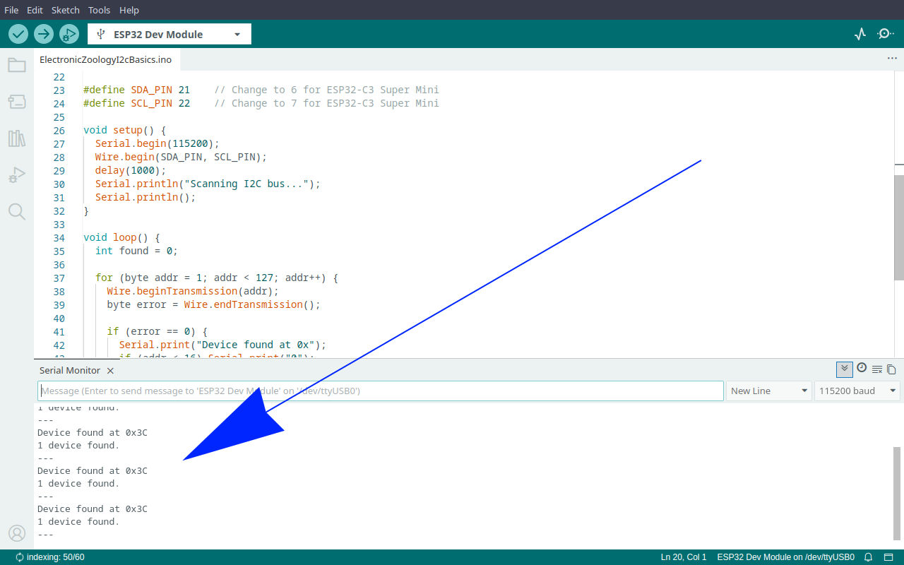
A device found on the bus looks like this in Serial Monitor:
Scanning I2C bus...

Device found at 0x3C
1 device found.
---
Note that address. It goes directly into your project sketch wherever the library asks for an I2C address. For the Adafruit SSD1306 library that is SCREEN_ADDRESS. For the INA219 library it is the address argument passed to begin(). Check your library's documentation if you are not sure where it goes.
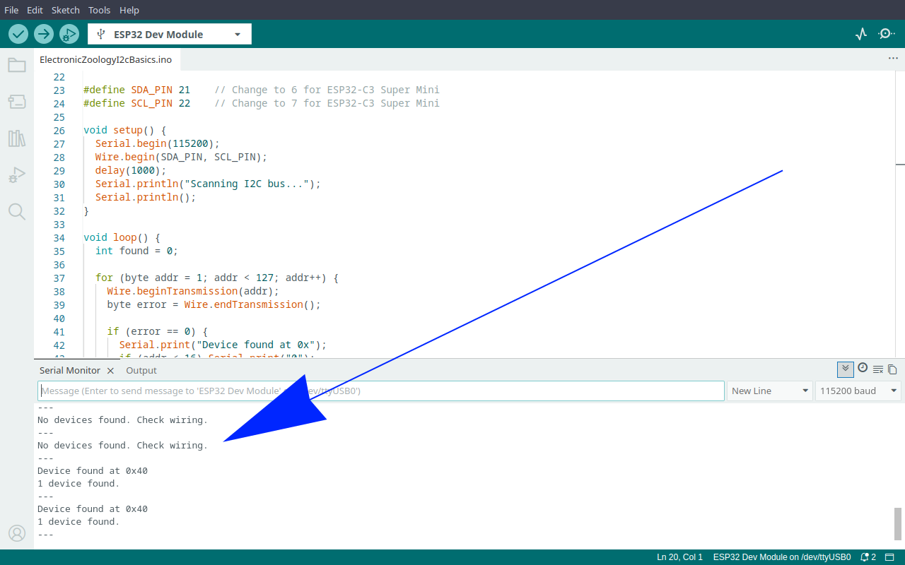
If the scan reports nothing:
No devices found
- SDA and SCL swapped is the most common cause. Swap the two signal wires and scan again.
- Check that VCC is connected and the device is powered.
- Some devices need pull-up resistors on SDA and SCL (typically 4.7k to 3.3V). Many breakout modules include these on-board. If yours does not, add them.
- A few devices need a short delay after power-on before they respond. The one-second
delay(1000)insetup()covers most cases.
Found at an unexpected address
- Check the address select jumper on the back of the module. The silkscreen will show which pad to bridge for each address.
- Some datasheets use 8-bit notation. If your datasheet says 0x78, the 7-bit address is 0x3C - right-shift by one bit.
Going Further
Put the address to use with an SSD1306 OLED
Once you have confirmed the address the next step is putting it to work. The SSD1306 is one of the most common I2C devices in ESP32 projects. The full guide covers library setup, wiring, and a test sketch that uses the address the scanner just gave you. See How to use the SSD1306 OLED display with ESP32 →
Add an INA219 current sensor
The INA219 is another common I2C device - default address 0x40, with alternate addresses available via a solder jumper if you need two on the same bus. The charger monitor guide wires an INA219 inline on a TP4056 charge line and displays live voltage and current on an SSD1306 OLED. Two I2C devices, two addresses, one bus. See How to build an INA219 battery charger monitor with ESP32 and OLED →