How to use the SSD1306
OLED display with ESP32
What this guide builds on
- How to check a new ESP32 - board setup in Arduino IDE, confirming the board is working before you build on it
- How to find your I2C address - how I2C addressing works and how to scan the bus to confirm your device is connected before writing a single line of project code
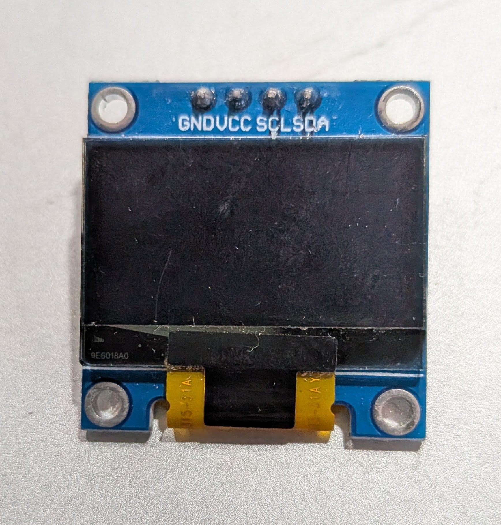
The 4-pin SSD1306 OLED needs only two signal wires - SDA and SCL. No chip select, no data/command pin, no SPI bus to share. It runs on 3.3V, draws very little power, and is readable in direct light without a backlight. It works well for status readouts, sensor values, and debug output in any project where colour is not needed.
This guide covers the 0.96 inch 128x64 module. The 0.91 inch 128x32 variant works with the same library and wiring - just change SCREEN_HEIGHT to 32.
What You Need
Parts
- ESP32 Dev Board (38-pin)
- SSD1306 128x64 OLED (4-pin I2C)
- Jumper wires
- USB data cable for flashing
Software
- Arduino IDE with ESP32 board support
Adafruit SSD1306by AdafruitAdafruit GFX Libraryby Adafruit (dependency)
Install via Arduino IDE Library Manager. When prompted to install dependencies, click Install All.
How It Works
The Adafruit SSD1306 library keeps a copy of the entire display in a 1KB frame buffer in the ESP32's RAM. Drawing calls write into that buffer. Nothing appears on screen until you call display.display(), which pushes the full buffer over I2C. To learn more about how ESP32 RAM works, see How ESP32 RAM works →
The workflow for every frame is always the same:
clearDisplay() → draw everything → display()
Skipping clearDisplay() leaves old content underneath new content. Skipping display() means nothing appears on screen. These two are the source of most first-run confusion.
Wiring
| OLED Pin | ESP32 Pin | Notes |
|---|---|---|
| VCC | 3.3V | Some modules accept 5V - check your module. When in doubt use 3.3V. |
| GND | GND | |
| SCL | GPIO 22 | I2C clock - hardware default |
| SDA | GPIO 21 | I2C data - hardware default |
Find Your I2C Address
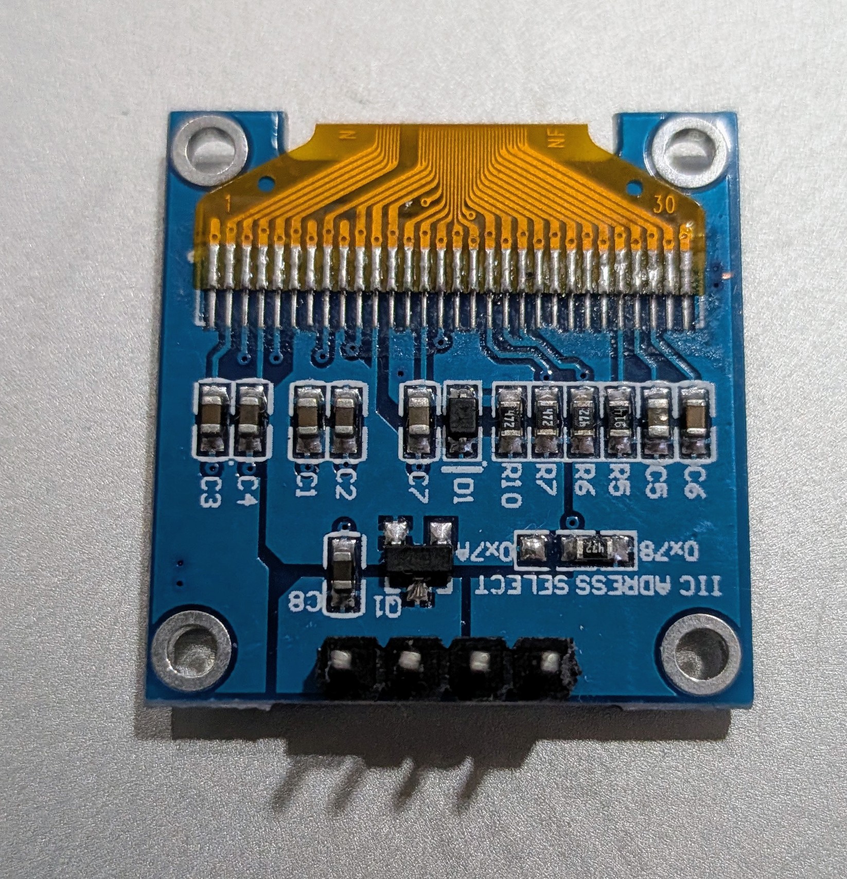
The SSD1306 is almost always 0x3C, but some modules ship as 0x3D. The address select jumper on the back of the module controls this - but flash the scanner below to confirm before going further. It also verifies your wiring is correct.
Open Serial Monitor at 115200 baud after flashing. If nothing is found, check wiring - SDA and SCL swapped is the most common cause.
/*
 * We stand on the shoulders of giants when we build
 * with knowledge gained from others' efforts.
 * That doesn't make us giants. Be humble.
 * Create with care. Open source is the way.
 *
 * I2C Address Scanner
 * --------------------
 * Reports all devices found on the I2C bus to Serial Monitor.
 * Open Serial Monitor at 115200 baud.
 *
 * Board:  ESP32 Dev Board (38-pin)
 * SDA:    GPIO 21
 * SCL:    GPIO 22
 *
 * Open source - MIT Licence
 * Electronic Zoology - field notes from the garage
 * https://electroniczoology.com/guides/how-to-use-ssd1306-oled-esp32
 */

#include <Wire.h>

void setup() {
  Serial.begin(115200);
  Wire.begin(21, 22);
  delay(1000);
  Serial.println("Scanning I2C bus...");
  Serial.println();
}

void loop() {
  int found = 0;

  for (byte addr = 1; addr < 127; addr++) {
    Wire.beginTransmission(addr);
    byte error = Wire.endTransmission();

    if (error == 0) {
      Serial.print("Device found at 0x");
      if (addr < 16) Serial.print("0");
      Serial.println(addr, HEX);
      found++;
    }
  }

  if (found == 0) {
    Serial.println("No devices found. Check wiring.");
  } else {
    Serial.print(found);
    Serial.println(found == 1 ? " device found." : " devices found.");
  }

  Serial.println("---");
  delay(3000);
}Note the address the scanner reports - you will need it in the next step.
Test Sketch
Update SCREEN_ADDRESS to match what the scanner found. Flash and open Serial Monitor at 115200 baud - the sketch prints a confirmation if the display is not found.
The sketch flashes the screen white twice as a pixel test, then runs an 80-star warp speed starfield with the site name overlaid.
/*
 * We stand on the shoulders of giants when we build
 * with knowledge gained from others' efforts.
 * That doesn't make us giants. Be humble.
 * Create with care. Open source is the way.
 *
 * SSD1306 OLED - Display Test Sketch
 * ------------------------------------
 * Flashes white twice as a pixel test, then an
 * 80-star warp speed starfield with site name.
 *
 * Board:   ESP32 Dev Board (38-pin)
 * Display: SSD1306 128x64 OLED (4-pin I2C)
 * Library: Adafruit SSD1306 + Adafruit GFX
 *
 * Wiring:
 *   VCC -> 3.3V    GND -> GND
 *   SDA -> GPIO 21  SCL -> GPIO 22
 *
 * Update SCREEN_ADDRESS to match your module (0x3C or 0x3D).
 * Run the I2C scanner above if unsure.
 *
 * Open source - MIT Licence
 * Electronic Zoology - field notes from the garage
 * https://electroniczoology.com/guides/how-to-use-ssd1306-oled-esp32
 */

#include <Wire.h>
#include <Adafruit_GFX.h>
#include <Adafruit_SSD1306.h>

#define SCREEN_WIDTH   128
#define SCREEN_HEIGHT  64
#define OLED_RESET     -1
#define SCREEN_ADDRESS 0x3C     // Change to 0x3D if the scanner found that

#define NUM_STARS 80
#define SPEED     3.5f

Adafruit_SSD1306 display(SCREEN_WIDTH, SCREEN_HEIGHT, &Wire, OLED_RESET);

struct Star { float x, y, z; };
Star stars[NUM_STARS];

int CX, CY;

void resetStar(Star &s) {
  s.x = random(-CX, CX);
  s.y = random(-CY, CY);
  s.z = 240;
}

void printCentered(const char* text, int y, int textSize) {
  int textWidth = strlen(text) * 6 * textSize;
  display.setTextSize(textSize);
  display.setCursor((SCREEN_WIDTH - textWidth) / 2, y);
  display.print(text);
}

void drawTitle() {
  display.setTextColor(SSD1306_WHITE);
  printCentered("Electronic", CY - 18, 2);
  printCentered("Zoology",    CY + 2,  2);
}

void setup() {
  Serial.begin(115200);

  Wire.begin(21, 22);
  Wire.setClock(400000);

  if (!display.begin(SSD1306_SWITCHCAPVCC, SCREEN_ADDRESS)) {
    Serial.println("SSD1306 not found. Check wiring and SCREEN_ADDRESS.");
    while (true) delay(1000);
  }

  Serial.println("SSD1306 found. Running test.");

  CX = SCREEN_WIDTH  / 2;
  CY = SCREEN_HEIGHT / 2;

  randomSeed(analogRead(0));

  // Pixel test - flash white twice
  for (int i = 0; i < 2; i++) {
    display.fillScreen(SSD1306_WHITE);
    display.display();
    delay(2000);
    display.fillScreen(SSD1306_BLACK);
    display.display();
    delay(400);
  }

  // Seed stars at random depths so the field is full from the start
  for (int i = 0; i < NUM_STARS; i++) {
    resetStar(stars[i]);
    stars[i].z = random(1, 240);
  }
}

void loop() {
  display.clearDisplay();

  for (int i = 0; i < NUM_STARS; i++) {
    Star &s = stars[i];

    s.z -= SPEED;
    if (s.z <= 1) { resetStar(s); continue; }

    int sx = CX + (int)(s.x * (float)CX / s.z);
    int sy = CY + (int)(s.y * (float)CY / s.z);

    if (sx < 0 || sx >= SCREEN_WIDTH || sy < 0 || sy >= SCREEN_HEIGHT) {
      resetStar(s); continue;
    }

    if (s.z < 60) {
      display.fillCircle(sx, sy, 1, SSD1306_WHITE);
    } else {
      display.drawPixel(sx, sy, SSD1306_WHITE);
    }
  }

  drawTitle();
  display.display();
  delay(1);
}Troubleshooting
Nothing on screen - display stays black
- Run the scanner from the step above first. If it finds nothing, the problem is wiring - SDA and SCL swapped is the most common cause.
- If the scanner finds a device but the display stays black, check that
SCREEN_ADDRESSmatches what the scanner reported.
Serial Monitor shows "SSD1306 not found"
display.begin()failed. Either the address is wrong or the display is not responding on the bus.- Run the scanner, confirm the address, and check both signal wires are seated.
Garbled or partial display
- Check that Adafruit GFX is installed alongside Adafruit SSD1306.
- A missing GFX dependency can cause partial rendering without a compile error.
Display works but is slow or flickers
- Add
Wire.setClock(400000)afterWire.begin()to switch to 400kHz fast mode. - The default 100kHz pushes a full 128x64 frame noticeably slower.
Sketch compiled fine but nothing appears
- Confirm
display.display()is being called after your drawing code. Nothing reaches the screen until that call is made.