How to display custom
images on the GC9A01
What You Need
Hardware
Software
- Arduino IDE with ESP32 board support
Arduino_GFX_Libraryby Moon On Our Nation- Python 3 + Pillow - image converter
- Any image editor (GIMP, Photoshop, etc.)
Install on Arch Linux:
Copy and paste into terminal
sudo pacman -S python python-pillowOther systems:
Copy and paste into terminal
pip3 install PillowHow It Works
The GC9A01 speaks RGB565 - each pixel is a 16-bit number encoding red (5 bits), green (6 bits), and blue (5 bits). Standard image formats like PNG and JPEG can't be sent directly - they need to be decoded and converted first.
The process is: resize your image to 240x240, run a Python script to convert every pixel to its RGB565 value, and write the result out as a C header file. The sketch includes that header and blits the pixel array straight to the display in one call.
Prepare Your Image
The converter will resize any image to 240x240 automatically, but you'll get better results doing it yourself first - it lets you control how it's cropped and centred.
In GIMP
- Open your image
- Image → Scale Image - scale so the shortest side is 240px
- Image → Canvas Size - set to 240x240 and centre the layer
- Image → Flatten Image - merges transparency to a solid background
- File → Export As - save as
.png
Convert to RGB565
Save this script as image_to_rgb565.py anywhere on your computer, then run it once per image. How to save a script →
#!/usr/bin/env python3
"""
Convert an image to an RGB565 C header for Arduino_GFX_Library.

Usage:
    python3 image_to_rgb565.py <image> <varname>

Example:
    python3 image_to_rgb565.py myface.png myface

Outputs: myface.h in the same folder as the image.
The image will be resized to 240x240 automatically.
"""

import sys
from pathlib import Path
from PIL import Image

def convert(img_path, varname):
    img = Image.open(img_path).convert("RGB")
    img = img.resize((240, 240), Image.LANCZOS)
    raw = img.tobytes()
    pixels = [(raw[i], raw[i+1], raw[i+2]) for i in range(0, len(raw), 3)]

    out_path = Path(img_path).parent / f"{varname}.h"
    with open(out_path, "w") as f:
        f.write(f"// {Path(img_path).name} -> 240x240 RGB565\n")
        f.write(f"#pragma once\n")
        f.write(f"const uint16_t {varname}[57600] = {{\n  ")

        for i, (r, g, b) in enumerate(pixels):
            val = ((r & 0xF8) << 8) | ((g & 0xFC) << 3) | (b >> 3)
            f.write(f"0x{val:04X}")
            if i < len(pixels) - 1:
                f.write(", ")
            if (i + 1) % 12 == 0:
                f.write("\n  ")

        f.write("\n};\n")

    print(f"Done -> {out_path}  (240x240, {240*240*2} bytes)")

if __name__ == "__main__":
    if len(sys.argv) != 3:
        print("Usage: python3 image_to_rgb565.py <image> <varname>")
        sys.exit(1)
convert(sys.argv[1], sys.argv[2])Run it
Replace the highlighted parts with your own values:
Copy and paste into terminal
python3 image_to_rgb565.py myface.png myfacepython3 image_to_rgb565.py myface.png myface
e.g. python3 image_to_rgb565.py ~/Downloads/thomasFaces/thomas1.png thomas1
This produces myface.h in the same folder as the image. Move it into your Arduino sketch folder alongside the .ino file.
myface.png- path to your image, e.g.~/Downloads/thomasFaces/thomas1.pngmyface- a name you choose for this image - no spaces, no special characters
Say you have an image in your photos folder called thomas1.png. You give the script thomas1 as the name. It creates a file called thomas1.h next to your image, and inside that file all the pixel data is stored in a variable also called thomas1. That variable name is what you put into the sketch - so the sketch knows what to draw.
The script uses the name for two things:
- The output filename -
thomas1becomesthomas1.h - The variable name declared inside that file -
const uint16_t thomas1[57600] = {...}
Call it whatever makes sense for your image. No spaces, no special characters.
The Sketch
Place myface.h in the same folder as the sketch. The top two lines are the only ones you change - update both myface references to match your varname.
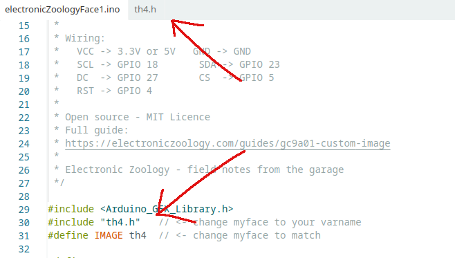
.h file appears as a tab in Arduino IDE, and the name in #include and #define both match exactly./*
* We stand on the shoulders of giants when we build
* with knowledge gained from others' efforts.
* That doesn't make us giants. Be humble.
* Create with care. Open source is the way.
*
* GC9A01 Custom Image Display
* ---------------------------
* Displays a custom RGB565 image on a GC9A01 240x240
* round IPS TFT display via SPI using Arduino_GFX_Library.
* Image is pre-converted from PNG using image_to_rgb565.py.
*
* Board: ESP32 Dev Board (38-pin)
* Library: Arduino_GFX_Library by Moon On Our Nation
*
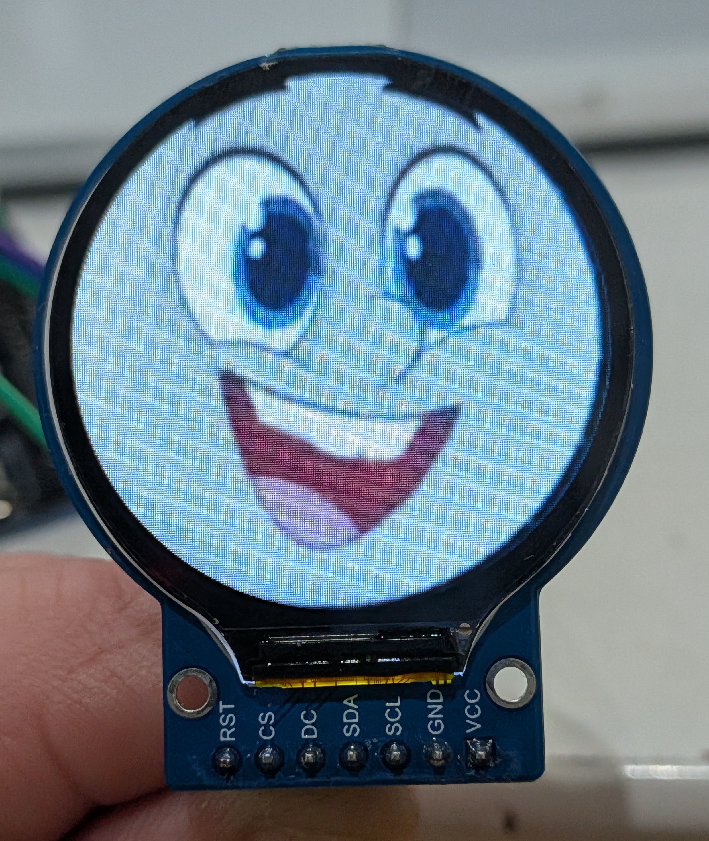
* Wiring:
* VCC -> 3.3V or 5V GND -> GND
* SCL -> GPIO 18 SDA -> GPIO 23
* DC -> GPIO 27 CS -> GPIO 5
* RST -> GPIO 4
*
* Open source - MIT Licence
* Full guide:
* https://electroniczoology.com/guides/how-to-display-images-gc9a01-esp32
*
* Electronic Zoology - field notes from the garage
*/
#include <Arduino_GFX_Library.h>
#include "myface.h" // <- change myface to your varname
#define IMAGE myface // <- change myface to match
#define TFT_DC 27
#define TFT_CS 5
#define TFT_RST 4
Arduino_DataBus *bus = new Arduino_HWSPI(TFT_DC, TFT_CS);
Arduino_GFX *gfx = new Arduino_GC9A01(bus, TFT_RST, 0, true);
void setup() {
Serial.begin(115200);
gfx->begin();
gfx->fillScreen(0x0000);
gfx->draw16bitRGBBitmap(0, 0, (uint16_t*)IMAGE, 240, 240);
}
void loop() {}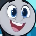
Troubleshooting
Wrong colours - image looks like a negative or has a red/blue swap
- RGB565 byte order matters - try swapping the bytes in the converter
- In
image_to_rgb565.py, change the val line to:val = ((val & 0xFF) << 8) | ((val >> 8) & 0xFF) - This byte-swaps each pixel to big-endian order which some display configs expect
Compile error - array too large / out of memory
- On ESP32,
constarrays are automatically stored in flash by the compiler - the 115KB array will not overflow RAM - see How ESP32 RAM works → to learn more - If you see this error, confirm your board is set to an ESP32 variant in Arduino IDE - AVR boards (Uno, Nano) do not have this behaviour and would need
PROGMEM
Image draws but is shifted, tiled, or has garbage at edges
- The image must be exactly 240x240 - check with
python3 -c "from PIL import Image; print(Image.open('myface.png').size)" - Rerun the converter after confirming the source image dimensions
Transparent areas showing as black or wrong colour
- Flatten the image in GIMP before exporting - Image → Flatten Image
- Set your desired background colour before flattening
- The converter uses
.convert("RGB")which drops the alpha channel - transparent pixels become black unless you flatten first
Display is blank after flashing
- Check the
#include "myface.h"filename matches exactly - Arduino IDE is case sensitive on Linux - Confirm the
.hfile is in the same folder as the.inofile - Open Serial Monitor - if nothing appears, the sketch may have crashed on boot